31 Consider The Following Diagram Of A Typical Motherboard Drag The Label On The Left
Drag the label on the left to the letter on the right that best identifies the associated connector. Expansion slots allow you to expand the capabilities and features of a computer by installing expansion cards.
 Building A Lightroom Pc Paulstamatiou Com
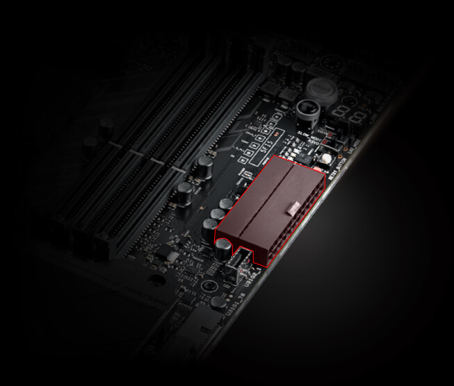
Atx power connector this is the second of two power connections.

Consider the following diagram of a typical motherboard drag the label on the left. Drag the label on the left to the letter on the right that best identifies the associated connector on the motherboard. Firmware is integrated software that is embedded in flash memory on the motherboard. Is a pcie x16.
Drag the label on the left to the letter on the right that best identifies the associated connector. A b pci e c pcie x16 f cpu power i pcie x1 g cpu j sata d h memory k fronttop panel case fan power power supply l usb ieee 1394 explanation the connectors on the motherboard have the following functions. Consider the following diagram of a typical motherboard.
The fan in a 450 watt power supply is malfunctioning. Using what you learned in this chapter and in chapter 1 label as many components as you can. Consider the internal connectors for a typical pc motherboard shown in the image below.
Used to connect pci expansion boards. Drag the label on the left to the letter on the right that best identifies the associated connector. Using them this way will give your memory a speed boost.
Consider the following diagram of a typical motherboard. Expansion slots allow you to expand the capabilities and features of a computer by installing expansion cards. Consider the following diagram of a typical motherboard.
Drag the label on the left and drop it on the letter on the right that best identifies the associated connector. Is a pcie x1. Drag the label on the left letter on the right that best identifies the associated connector.
Flash memory nonvolatile bios memory explanation a typical motherboard includes the following components. Firmware is integrated software that is embedded in flash memory on the motherboard. The color coding you see on the motherboard diagram is used to match up ram for dual channel.
Labeling the motherboard figure 4 58 shows a blank diagram of an atx motherboard. Diagram of a typical motherboard. Non volatile bios memory explanation a typical motherboard includes the following components.
This is the main power connection for the motherboard and comes from the power supply.
 3 3 2 Motherboard Facts 3 3 2 Motherboard Facts A Motherboard
 Ee Times Electronic Engineering Times Connecting The Global
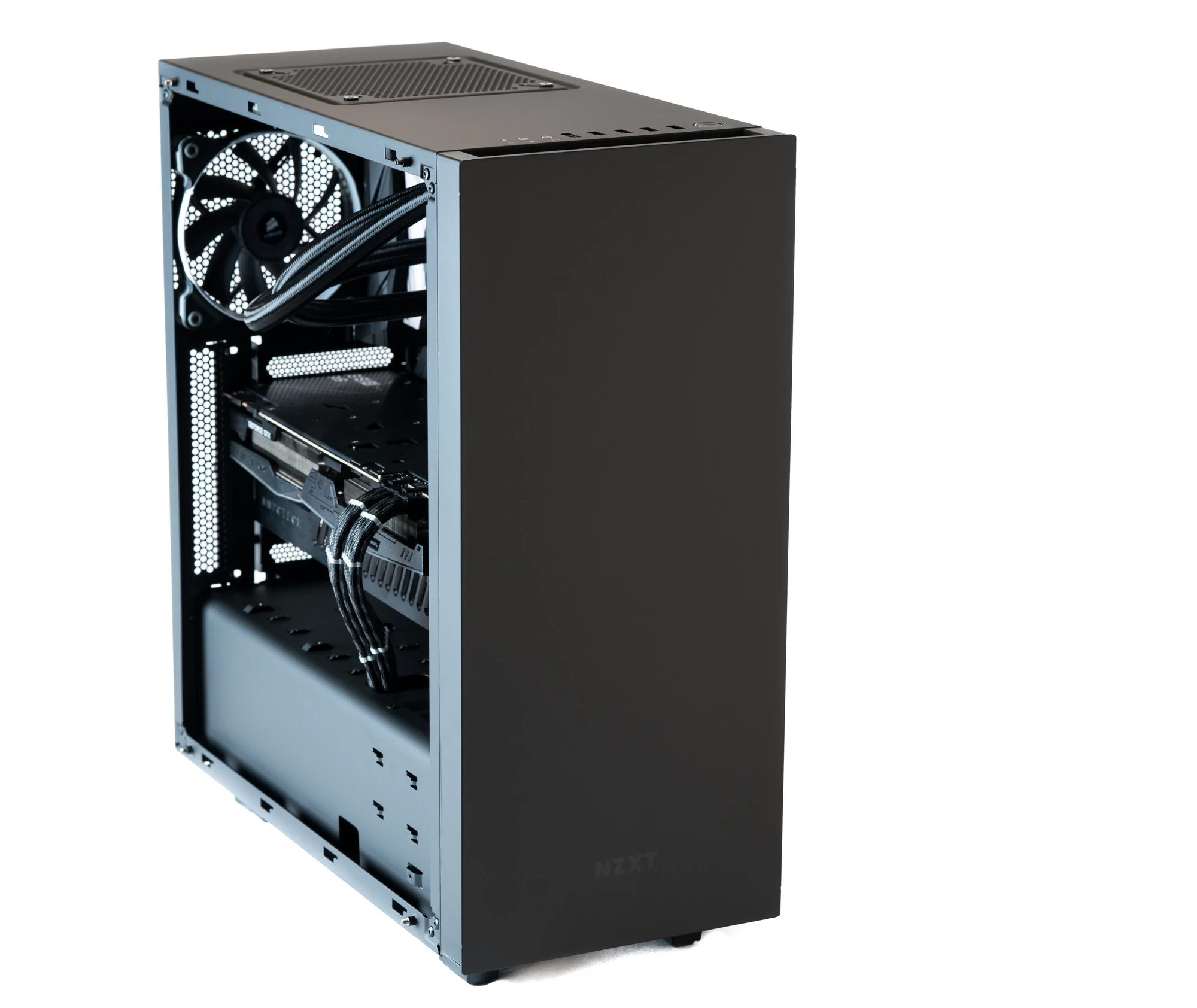 Building A Lightroom Pc Paulstamatiou Com
 Latest Blogposts Yahoo Developer Network
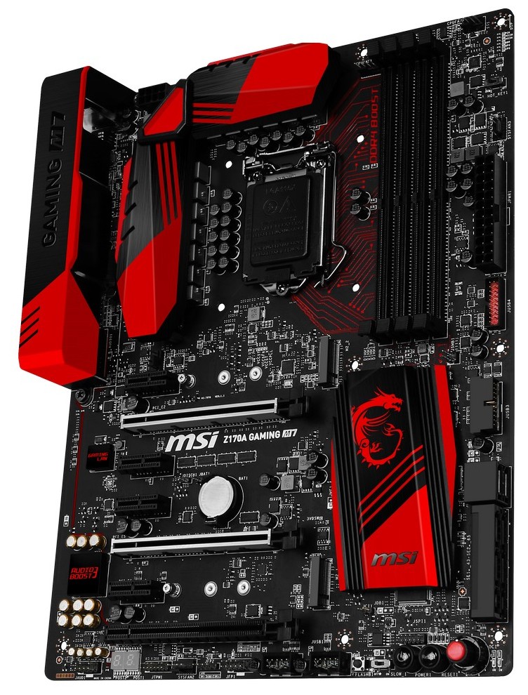 Board Features In The Box Visual Inspection Test Setup The
 Enabling Framework For Structural Health Monitoring Using Smart
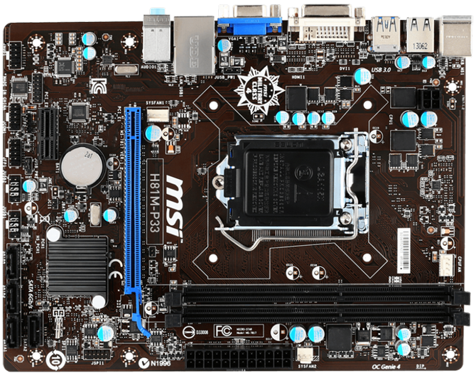 A Short Guide To Motherboard Parts And Their Functions
 Sc16a Servo Controller User S Manual Cytron Technologies
 Dell Latitude 15 3590 Improvement Over Last Year S Fluke But Not
 Gigabyte P57x V7 Gaming Notebook Review Notebookcheck Net Reviews
 Prime X570 P Motherboards Asus Usa
 Teax Thermalcapture Thermal Imaging Technology
 Cisco And Sas Edge To Enterprise Iot Analytics Platform Cisco
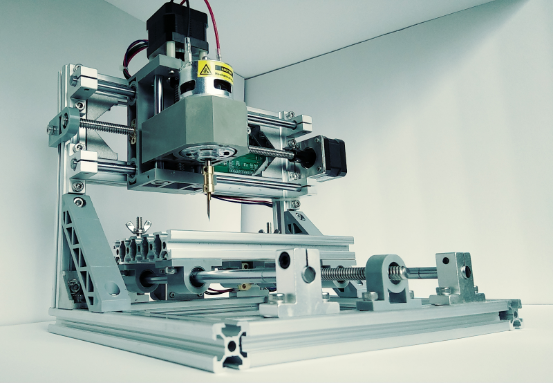 Review Linksprite Mini Cnc Hackaday
Introducing Adafruit Crickit Makerobotfriend
 Iot Diy Projects 2019 Overview Of Internet Of Things Projects
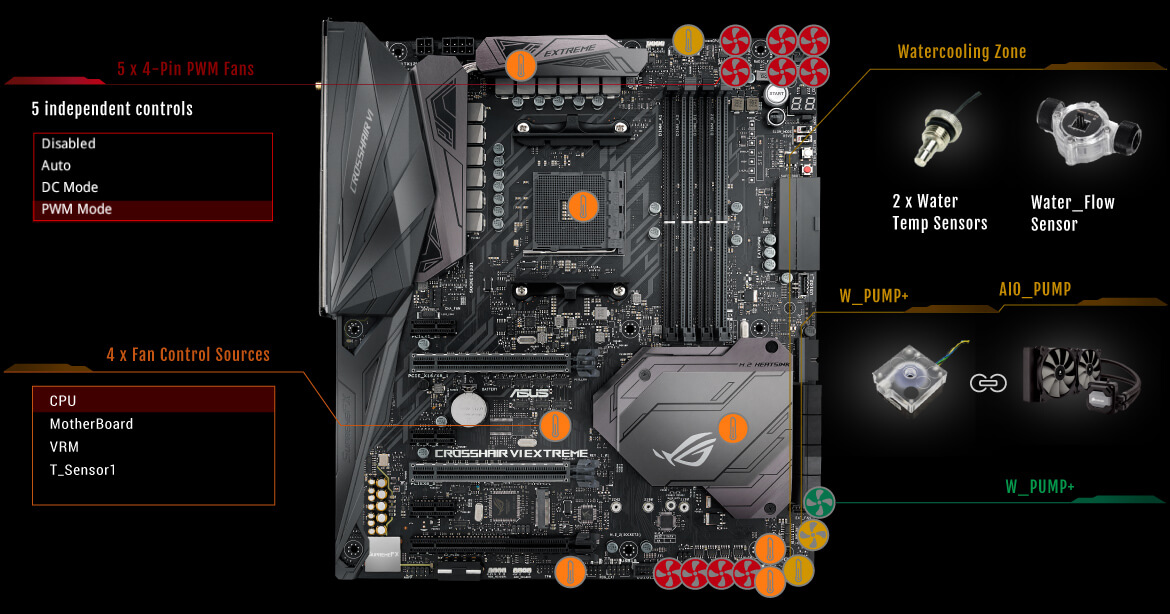 14 January 2019 Techbuy Australia
These Forums Convene Residents From Communities
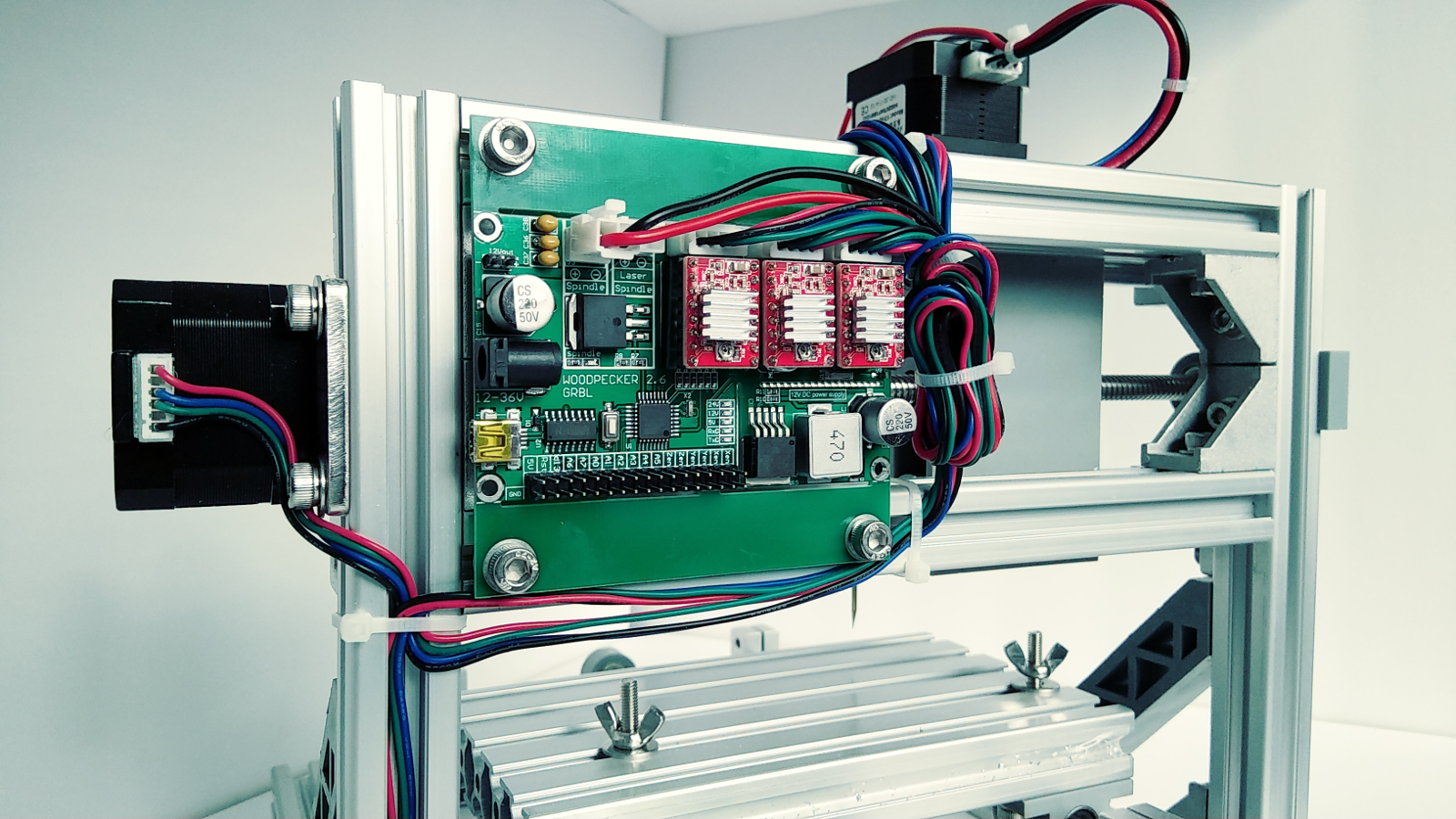 Review Linksprite Mini Cnc Hackaday
 How To Assemble A Desktop Pc Choosing The Parts Wikibooks Open
 Dell Latitude 15 3590 Improvement Over Last Year S Fluke But Not
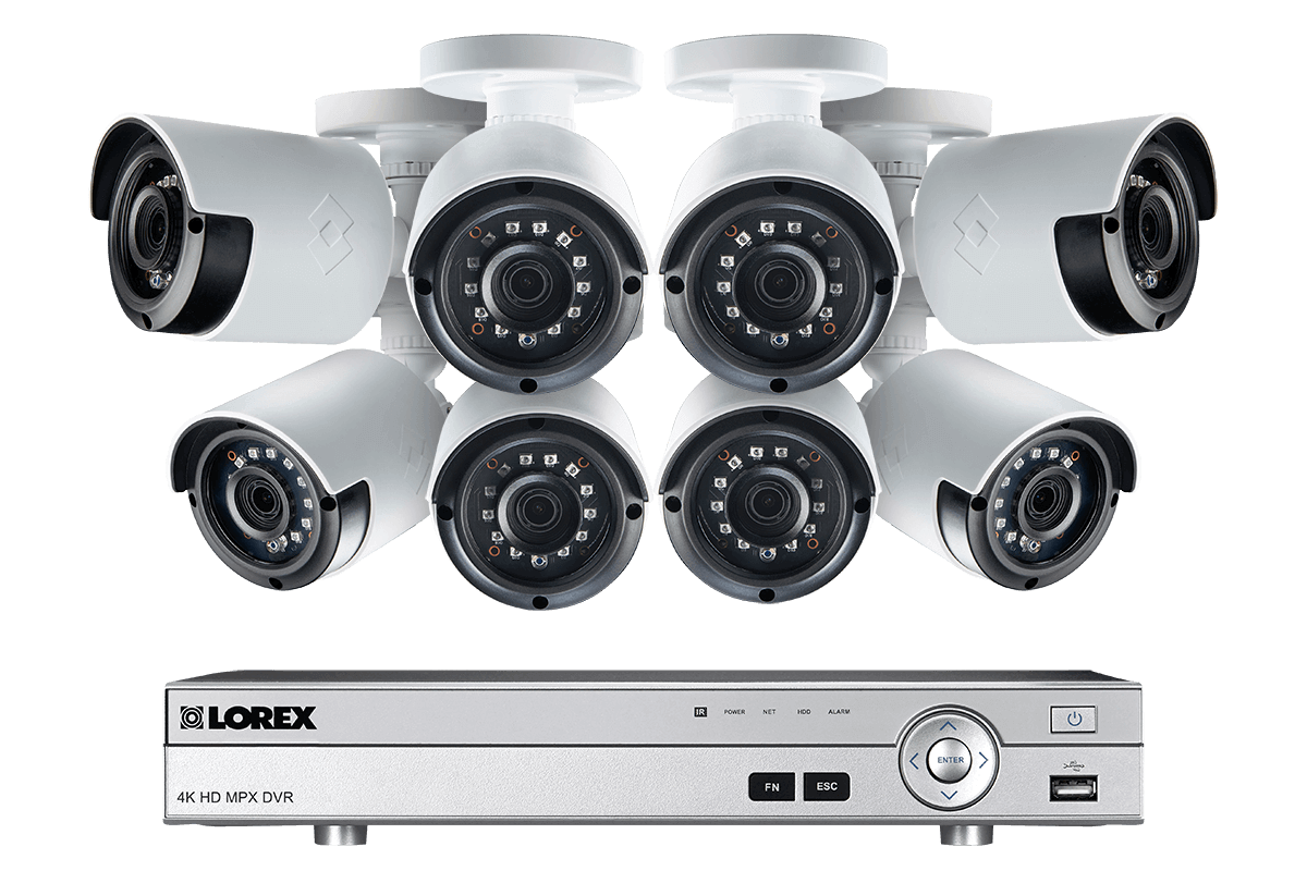 1080p Camera System With 8 Channel Dvr And 8 1080p Outdoor Security Cameras 130ft Night Vision 1tb Hard Drive
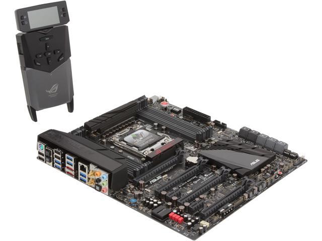 Asus Rog Rampage Iv Black Edition Lga 2011 Intel X79 Sata 6gb S Usb 3 0 Extended Atx Intel Gaming Motherboard
 Getting Started With Raspberry Pi Paulstamatiou Com
 14 January 2019 Techbuy Australia
 Building A Lightroom Pc Paulstamatiou Com



Post a Comment for "31 Consider The Following Diagram Of A Typical Motherboard Drag The Label On The Left"